If you need assistance, please send an email to forum at 4hv dot org. To ensure your email is not marked as spam, please include the phrase "4hv help" in the subject line. You can also find assistance via IRC, at irc.shadowworld.net, room #hvcomm.
Support 4hv.org!
Donate:
4hv.org is hosted on a dedicated server. Unfortunately, this server costs and we rely on the help of site members to keep 4hv.org running. Please consider donating. We will place your name on the thanks list and you'll be helping to keep 4hv.org alive and free for everyone. Members whose names appear in red bold have donated recently. Green bold denotes those who have recently donated to keep the server carbon neutral.
Special Thanks To:
Aaron Holmes
Aaron Wheeler
Adam Horden
Alan Scrimgeour
Andre
Andrew Haynes
Anonymous000
asabase
Austin Weil
barney
Barry
Bert Hickman
Bill Kukowski
Blitzorn
Brandon Paradelas
Bruce Bowling
BubeeMike
Byong Park
Cesiumsponge
Chris F.
Chris Hooper
Corey Worthington
Derek Woodroffe
Dalus
Dan Strother
Daniel Davis
Daniel Uhrenholt
datasheetarchive
Dave Billington
Dave Marshall
David F.
Dennis Rogers
drelectrix
Dr. John Gudenas
Dr. Spark
E.TexasTesla
eastvoltresearch
Eirik Taylor
Erik Dyakov
Erlend^SE
Finn Hammer
Firebug24k
GalliumMan
Gary Peterson
George Slade
GhostNull
Gordon Mcknight
Graham Armitage
Grant
GreySoul
Henry H
IamSmooth
In memory of Leo Powning
Jacob Cash
James Howells
James Pawson
Jeff Greenfield
Jeff Thomas
Jesse Frost
Jim Mitchell
jlr134
Joe Mastroianni
John Forcina
John Oberg
John Willcutt
Jon Newcomb
klugesmith
Leslie Wright
Lutz Hoffman
Mads Barnkob
Martin King
Mats Karlsson
Matt Gibson
Matthew Guidry
mbd
Michael D'Angelo
Mikkel
mileswaldron
mister_rf
Neil Foster
Nick de Smith
Nick Soroka
nicklenorp
Nik
Norman Stanley
Patrick Coleman
Paul Brodie
Paul Jordan
Paul Montgomery
Ped
Peter Krogen
Peter Terren
PhilGood
Richard Feldman
Robert Bush
Royce Bailey
Scott Fusare
Scott Newman
smiffy
Stella
Steven Busic
Steve Conner
Steve Jones
Steve Ward
Sulaiman
Thomas Coyle
Thomas A. Wallace
Thomas W
Timo
Torch
Ulf Jonsson
vasil
Vaxian
vladi mazzilli
wastehl
Weston
William Kim
William N.
William Stehl
Wesley Venis
The aforementioned have contributed financially to the continuing triumph of 4hv.org. They are deserving of my most heartfelt thanks.
Registered Member #2099
Joined: Wed Apr 29 2009, 12:22AM
Location: Los Altos, California
Posts: 1714
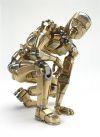
Any HFHV enthusiasts got time to read the misleadingly named thread "Bridge Rectifier Circuit" in HV forum, and pitch in for andre's and my benefit? Clearly my pictures and andre's schematic have a wire missing from the left end of the voltage multiplier stack. thanks Rich
Registered Member #3414
Joined: Sun Nov 14 2010, 05:05PM
Location: UK
Posts: 4245
Why do you say there is clearly a wire missing? It looks to me like it should work 'as is'.
EDIT: Brown wires are one terminal (one wire has series resistance, this is the one to connect to, I imagine, as it limits the current). Red and White are the other terminal. Use the Red and the Brown connected via the resistors as your terminals.
I assume this works in flyback mode.
C7 is just a shunt, it doesn't form part of the multiplier, I think.
It is a resonant circuit. I think it works like a self-resonant transformer, one with an external capacitor. The frequency you run this at is 'critical', but it is pretty straightforward to measure the resonant frequency, but I think you'd need to get the soldering iron out.
The 'correct' frequency 'could' be a 'third harmonic', or something, or it may just be resonance.
EDIT: I don't know that I'm completely correct, so I posted here, rather than in the main thread)
Registered Member #33
Joined: Sat Feb 04 2006, 01:31PM
Location: Norway
Posts: 971
Brown wires are one terminal (one wire has series resistance, this is the one to connect to, I imagine, as it limits the current). Red and White are the other terminal. Use the Red and the Brown connected via the resistors as your terminals.
This would not work at all, all the wires on the right side only share a single node with the high voltage multiplier.
The load connects between the left side of C1 and the upper brown wire in the diagram. In the original circuit, the x-ray tube cathode would have connected to the lower brown wire and the voltage drop over the resistors would serve as the bias voltage for the filament cup, which would be connected to the upper brown wire. The role of C7 is to smooth this voltage.
Klugesmith's analysis is correct, the circuit is simply three separate secondaries, each with its own voltage doubler on the output. The outputs of these doublers are connected in series. They do it this way to increase the resonant frequency of the transformer and to lower the demands on the insulation (DC is much easier on the insulation than HF AC). It's basically the same principle as a diode-split flyback, but with doubling and smoothing for each secondary.
The transformer is probably supposed to be driven by a resonant topology on account of the likely high reflected secondary capacitance. Definitely not flyback.
Thank you for the video it explains a lot, so the description on ebay is wrong, is just 3 12.5KV coils and they are using diodes and caps to double the voltage. so according to the video this is how it should be connected. and the feedback is negative
Registered Member #2099
Joined: Wed Apr 29 2009, 12:22AM
Location: Los Altos, California
Posts: 1714
Right, Andre (your picture of + and -, and the comment about coils being only 12.5 kV).
I should not have split this thread into two, especially in two different forums. Had been afraid that the title "Bridge rectifier" would be skipped by expert readers. Sorry.
It's ironic that this kind of voltage doubler has a schematic identical to that of a bridge rectifier, except for 2 capacitors in place of 2 diodes. I had never noticed that, before watching that fine old tutorial in Wolfram's link. Good find!
The film is very clear, and is properly paced for the lecture hall. Two caveats for the newbies:
1: We are talking about a -symmetric- voltage doubler circuit. Internet searches are more likely to turn up a different voltage doubler configuration, of which MWO power supplies are a ubiquitous example. In that circuit, one end of secondary is common with one end of the load, and the other end connects only to a capacitor.
2: (Rich steps onto soapbox). In the film, the instructor's pointer and the animation show the direction of current as the direction of electron flow. That seemed natural and "correct" for me too, up to about the age of 12. But the opposite convention is practically universal in two centuries of literature and discourse about electric current. And it is not "wrong".
IMHO, reading and talking about electric current will be much easier if you practice thinking of it as motion of positive charge. That model works fine for understanding electromagnetic fields and waves, circuits, and external behavior of all components. The international units of measurement (V,A,ohm,F,H,etc.) were standardized before the discovery of electrons. Electric lighting and telephone systems and 3-phase AC power networks and utility tariffs (regulated and taxed) were working productively, before anyone knew the sign of charge carriers in metallic conductors.
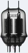
You will need to "flip" and think in terms of moving electrons when dealing with the internal workings of electron tubes and some semiconductor devices.
Registered Member #3414
Joined: Sun Nov 14 2010, 05:05PM
Location: UK
Posts: 4245
klugesmith wrote ...
IMHO, reading and talking about electric current will be much easier if you practice thinking of it as motion of positive charge. That model works fine for understanding electromagnetic fields and waves, circuits, and external behavior of all components. The international units of measurement (V,A,ohm,F,H,etc.) were standardized before the discovery of electrons. Electric lighting and telephone systems and 3-phase AC power networks and utility tariffs (regulated and taxed) were working productively, before anyone knew the sign of charge carriers in metallic conductors.
You will need to "flip" and think in terms of moving electrons when dealing with the internal workings of electron tubes and some semiconductor devices.
I apoligise for posting slightly OT, Rich, but I assume this thread has pretty much run it's course now.
While we're on the subject of charge carriers, are the 'holes' talked about so much in reference to semi-conductors just areas of low electron density, which 'appear' to move in the opposite direction to electrons, or are they actually 'holes that move'? I've never been able to properly understand this.
Registered Member #30
Joined: Fri Feb 03 2006, 10:52AM
Location: Glasgow, Scotland
Posts: 6706
Each hole is one "absence of electron" from the crystal lattice. Think of it as the missing piece in one of those puzzles with the 15 square pieces you can slide around. If all 16 were present, none of them could move.
When you play this puzzle game, are you moving the tiles, or the hole? Does the question even make sense?
This site is powered by e107, which is released under the GNU GPL License. All work on this site, except where otherwise noted, is licensed under a Creative Commons Attribution-ShareAlike 2.5 License. By submitting any information to this site, you agree that anything submitted will be so licensed. Please read our Disclaimer and Policies page for information on your rights and responsibilities regarding this site.


 Reverse-engineering a voltage multiplier from x-ray source